How to solve the occlusion phenomenon of drone orthophoto
Orthophotography: Remote sensing imagery with both the geometric accuracy of the map and the visual characteristics of the image. It is not so easy to obtain satisfactory drone orthophoto images, so this article mainly briefly introduces the solution to the occlusion phenomenon of UAV orthophoto images.
1) The concept of occlusion
The occlusion mentioned here is the occlusion, which refers to the phenomenon that the local area on the ground is invisible on the image due to the occlusion of the target object with a certain height on the ground. There are two main types of shading on aerial remote sensing images. One is absolute shading. For example, tall trees occlude low buildings, making the occluded buildings invisible on aerial remote sensing images. The other is relative occlusion, as shown in Figure 1, for the △ABE area on the ground, it is not visible on the right photo, that is, it is occluded, but△CDF it is visible on the left photo.

Figure 1 Schematic diagram of relative shading
Processing method of UAV drone orthophoto to occlusion phenomenon
In order to effectively weaken or eliminate the influence of occlusion on orthophotos as much as possible, so that orthophoto products meet the geometric accuracy requirements of the corresponding scale map, people have proposed many methods to solve the occlusion phenomenon, the main strategies include the following:
(1) Image data collection
By using long focal length photography, increasing the photography flight height, shortening the photography baseline, etc. to increase the overlap of the photos, and try to avoid the high-rise buildings falling on the edge of the photo when designing the aerial photography flight route. , reduce the projection difference (shading) caused by the target object with a certain height on the ground, that is, reduce the scope of shading on the photo.
(2) Data correction
Try to use the middle part of the photographic photo to make an orthophoto, because the middle part of the central projection photo has a small or no projection difference, in other words, the shading range here is small or no shading at all.
(3) Select the sensor
As the line array scanning imaging sensor is widely used, people hope to use the line array scanning sensor image to make an orthophoto. Because for the vertical line-of-sight array scanning image, the target with a certain height on the ground will only produce a projection difference in the direction perpendicular to the flight of the sensor platform
The real radiographic image is to perform digital differential correction based on the digital surface model (DSM) in the process of digital differential correction.
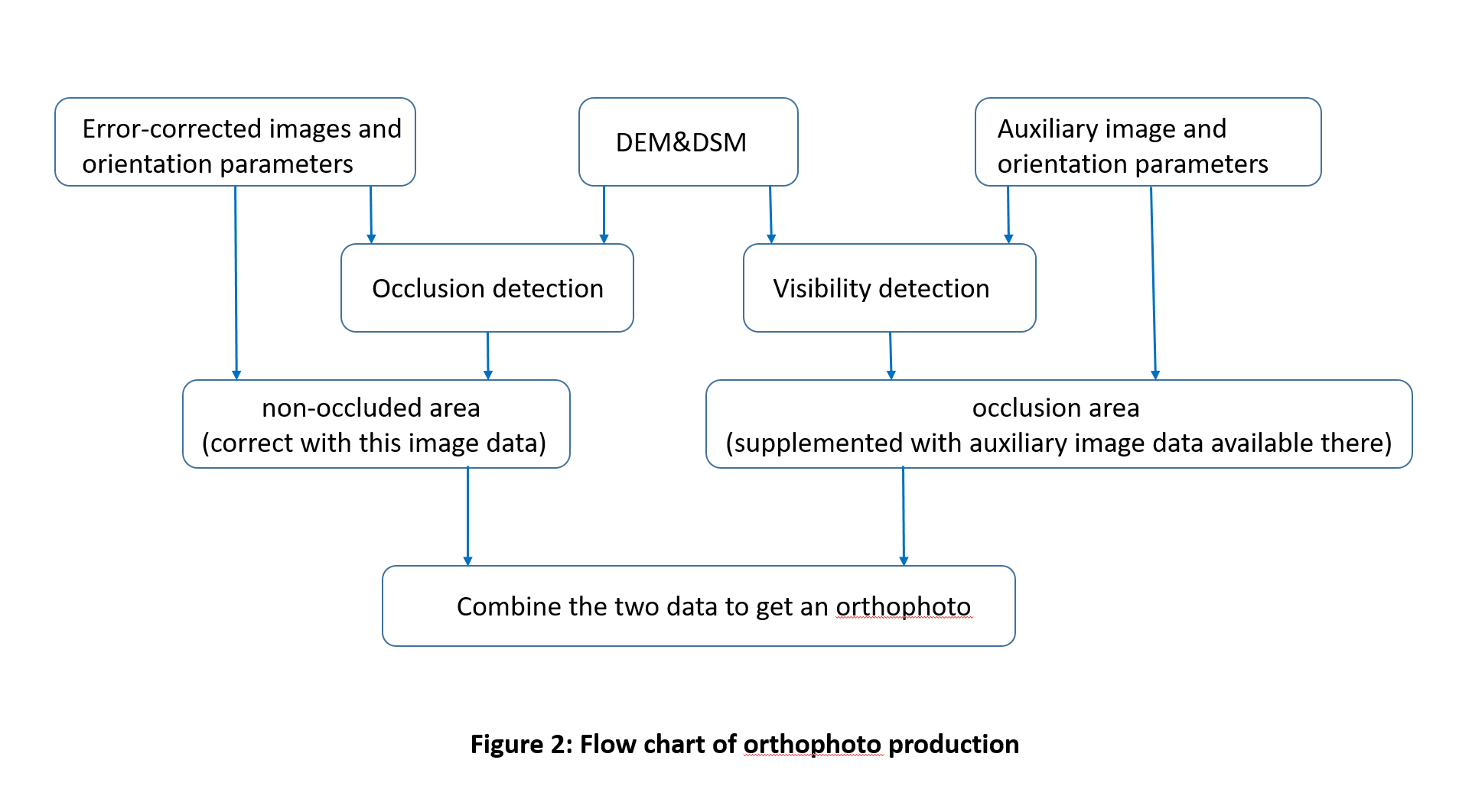
The specific production process of the orthophoto can be represented by the flowchart shown in FIG. 2 .

The flow chart is explained as follows: In the photo with multi-angle overlap, select one image as the main correction image, and other images as auxiliary images to compensate the information of the occluded part of the main correction image, that is, in the auxiliary image. The information of the corresponding part of the image is filled into the masked area of the main corrected image. Of course, the premise of this is that the shaded areas on the main corrected image must be visible on the subordinate images. Otherwise, the information of the shaded areas can only be filled and compensated by other methods, such as using the texture of the adjacent area to perform filling compensation, regardless of whether What method is used to fill and compensate the information of the masked area of the main correction image should take into account the coordination of the filled content and its surroundings in terms of brightness, color and texture.
However, the process of making orthophotos described in Figure 2 is still somewhat idealized, because the actual ground surface is complicated, and it is not a simple task in terms of DSM acquisition or compensation of occlusion information.
With the development of digital aerial cameras and the widespread use of digital aerial photography technology, the overlapping degree of flight can be improved during aerial photography. While improving the accuracy of ground positioning, the local image near the bottom point of each image can be fully utilized to create an orthophoto, which can avoid the trouble of filling the missing information of the image.
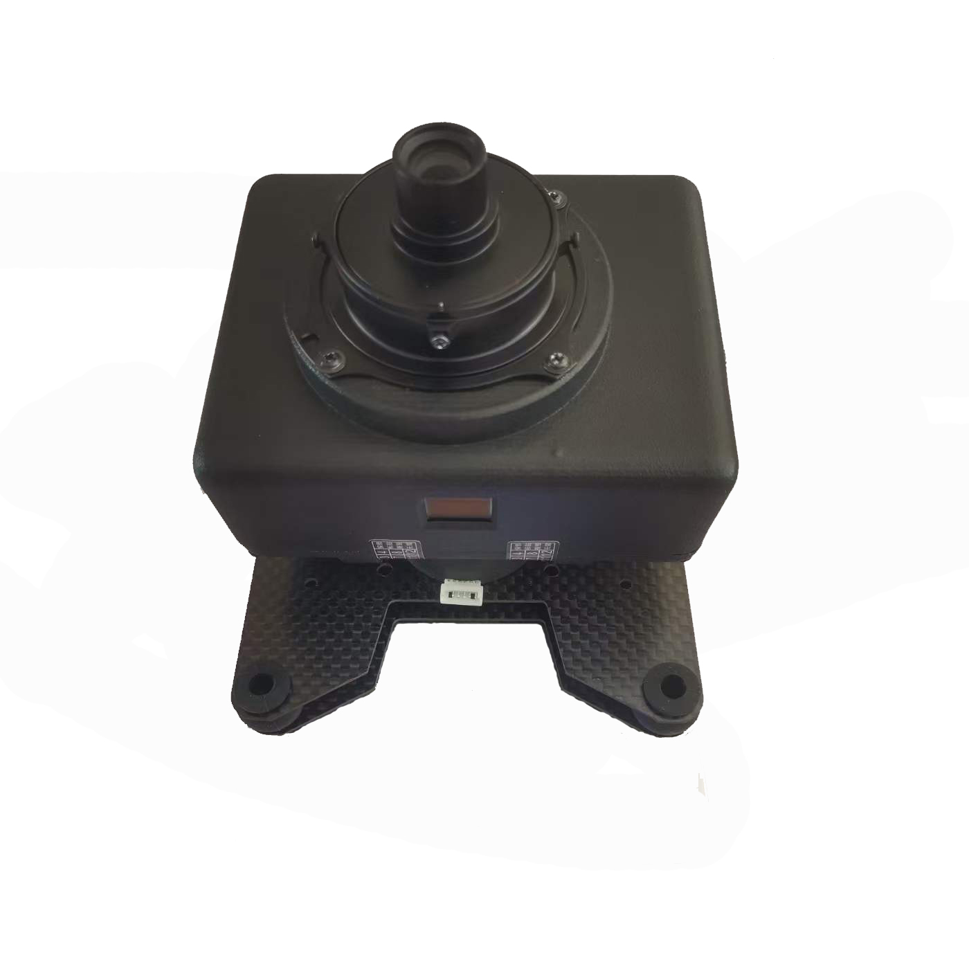
A7R II 35mm lens 42 MP Full Frame orthophoto Camera

Sensor: Full –frame exmor CMOS sensor(35.8*23.9mm)
Pixels: 42.4MP
Pixel Size: 4.5μm
Image size(pixels): 7952*5304
Hot shoe: supported
Shutter trigger: High level, low level(by default) /PWM
Shutter speed: 30-1/8000sec(adjustable)
Minimum exposure time: 0.8s
Parameter setting: Button/USB
Data reading: SD card/USB
Storage: SD card(Max 128G)
Power: 7.2-8.6V
Size:95*75*43mm
Weight:219g(standard)
Interface: HDMI/USB/SD card slot/Hot shoe


