How to DIY 4 rotor drone
Every time I go out to play the airplane model, I will be watched by many people. The layman will ask, "Boy! Did you make this plane by yourself? How high can you fly? How far can you fly? Can you burn oil? Why don't you make it with iron ... it's done ... I will also boast that this guy is so powerful! If you know a little, I will ask! Four-rotor! What flight control is used? What configuration? What camera is attached? Single control or dual control? ... If you are a novice, if you want to After watching, after reading this fool tutorial, you can also diy your own drone!

There are many kinds of drones, such as multi-rotor, channel, turbojet and so on. The more mainstream is the multi-rotor, because she can perform aerial photography tasks. So let's briefly talk about how to assemble an entry-level four-rotor drone!
 Quadcopters
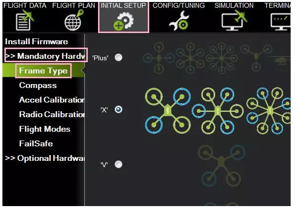
 are mainly divided into two types: "+" type cross and "×" type cross. We chose the "×" cross to keep the field of view in front of the camera undisturbed.

We will introduce one by one how to make the fuselage, install the flight control system ArduPilot, so that the aircraft can fly automatically. After installation, you can set the path in advance, control the aircraft to fly to a series of coordinates, and take aerial photos for you.

Step 1: Build the fuselage
The central hub of the quadcopter is composed of two PC boards. Download the template for cutting and drilling here, output it at its original size, and temporarily paste it on the PC board. First use a plastic engraving knife to make a score, then drill with a 1/8 "drill bit.

Step 2: Cut the bracket and drill holes
Saw four 10 "–11" square wood tenon brackets. The shorter the arm, the more agile the aircraft, but the longer the arm, the more stable the aircraft. Drill two small holes of 3mm each, one 6mm from the end and the other 26mm from the end.

Step 3: Assemble the fuselage
Saw four 10 "–11" square wood tenon brackets. The shorter the arm, the more agile the aircraft, but the longer the arm, the more stable the aircraft. Drill two small holes of 3mm each, one 6mm from the end and the other 26mm from the end.

Step 4: Connect the power core
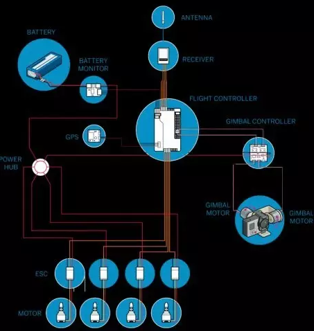
The power core consists of six parts: four electronic speed controllers, power modules and camera stabilizer control board. First, separate the XT60 male connector and the APM power module cable. Each red and black wire should be stripped of approximately ¼ "insulation and the end of the stripped wire is tinned. Saw ⅜" loops from both ends of the copper reducer, file the uneven edges, six red wires The positive terminal is welded to the inner ring, and the corresponding six black negative terminals are connected to the outer ring. The inner ring is wrapped with foam waterproof tape, and the outer ring is sleeved. Finally, apply insulating glue to the entire center.
Connecting motors and electronic speed controllers can be a tedious task. Buying a switchboard directly will save you time, but it will take up space and add weight. I prefer to make a self-made switchboard, which can be completed by using two loops of tapered copper tubes. It also looks very precise and neat.

Step 5: Drilling the motor base
Here I will teach you how to easily make a landing gear with a normal C-clamp. You can also buy a cheap combined landing gear / motor base to intermittently make the process.
If you plan to make your own landing bracket, you will need to install the motor directly on the bracket. First, mark each bracket and drill blind holes that are not obvious so that the motor shaft can rotate freely. Using a 5/16 "drill bit is a good choice.

Step 6: Install the motor
Cut the bracket of the motor, and fix the motor and the motor bracket to the rear end of the four-rotor bracket with two M3 × 20mm screws. You must tighten each screw tightly and ensure that the motor shaft can rotate freely. If it cannot rotate freely, check the groove of the four-rotor bracket again, and finally smooth the edges of the motor bracket with a file.

Step 7: Add landing gear
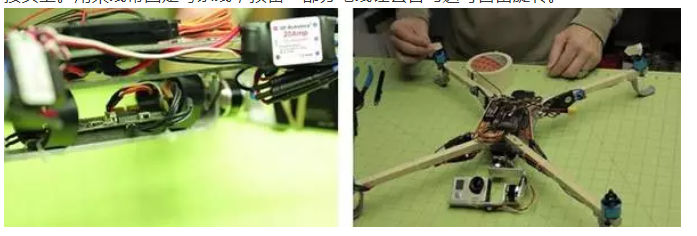
Slide the power core between the two transparent plates, and then wrap the power cable of the electronic transmission on the four brackets. If the manufacturer of the motor and the electronic transmission are the same, there may be a pre-installed "bullet" connector. At this time, directly insert the motor wire into the transmission wire, and the extra wire is coiled under the bracket. You can also solder the wires directly to the control board of the electronic transmission to intersect the structure. Fix the motor wire and the electronic transmission wire, and then tie the extra wires under the bracket with a cable tie.
Use wire cutters to cut the four C-shaped clips into halves, set the J-shaped base aside, smooth the cutting surface with a file, and then grind two small grooves on both sides of the mounting hole to install this base on each bracket The tail end of the motor frame, that is, the inner side of the motor frame, the cable tie bypasses the newly grinded groove.

Step 8: Install shock mount
Remove the water pipe retaining ring of the PVC hose and leave it for other topics. Using a pen-shaped utility knife, cut two 3/4 "plastic rings from the rubber hose, align the inner hole screws protruding from the fuselage, squeeze the thumb to form two indentations, and then use ⅛" The drill bit drills holes in the dent, but do not drill through the other side. Put the plastic ring on the fuselage with M3 flat washer and nut. After adjusting the tightness, fix it with screw sealant.
Cut the two anti-vibration mounts from the hose, and then use them to install the gimbal and battery mounts to prevent the camera from being affected by the propeller vibration. By the way, make a little space above to install the gimbal controller.

Step 9: Install the camera and battery holder
The Vientiane bracket and the battery bracket are mainly assembled from three sets of single L-shaped brackets. I call them brackets, roll axis and pitch axis brackets.
Sawing the aluminum rod (1/8 "× ¾" × 36 ") into two 18" aluminum strips, and then sawing one of them into 9 "aluminum strips, you will get a total of three aluminum strips. Each aluminum strip All are folded at right angles, and the wooden or aluminum block with beveled edges can be used to increase the bending radius to ⅜ "(curly bending may bring too much pressure to the aluminum strip, which may damage the support force of the aluminum strip). After the aluminum strip is bent, cut each bracket to the size of a foreign board.
Place the bracket on the correct installation position, mark and drill three 1/8 "radius holes in the center of the shorter end of the X-axis and Y-axis brackets. On both brackets, outside The small hole should be 3mm away from the end of the bracket, and the distance between the two small holes should be 9.5mm. Finally, use a step drill to expand the middle hole to 2 "large so that the motor shaft has room for rotation.
Fix the bottom of the gimbal motor to the bracket with two M3 × 6mm screws, and fix the top of the motor to the long side of the roll shaft bracket with two other screws.
Connect the bottom of the second motor to the other end of the roll shaft bracket, and the top of the motor to the pitch shaft bracket in the same way.

Step 10: Install the camera and battery
The quadcopter I designed can balance the weight of the 3S 2, 200mAh lithium battery and GoPro Hero3 white. If you use other equipment, please make sure your CG (center of gravity) is maintained in the center of the fuselage. The following demonstrates how to achieve balance.
Tip: Although the GoPro camera is quite drop-resistant, you may also want to make a "fake" camera with the same weight and size, which can be installed on the aircraft during the first and subsequent test flights.
For the gimbal motor to run smoothly, the camera must be balanced on both axes. First stick one side of the double-sided tape to your shirt to reduce its stickiness. Attach the other side of the tape to the tilt bracket, and then fix your GoPro to the weaker side. Slowly find the balance. Just use two screws to fix the motor on the bracket and cut the motor bracket. To reduce weight. Thick rubber hoses can be used to make two sets of anti-vibration devices, and direction controller brackets and battery brackets can also be made to prevent the camera from being affected by propeller vibration, and reserve space for the direction control board.
Put the frame upside down, so that the camera, bracket and battery are balanced at the center of the anti-shock device at the bottom of the frame. Adjust the position of the assembled device back and forth along the skeleton until the entire four-rotor device can achieve a balance point between your two fingers, and the balance point is also located at the center of either end.
After finding the center of gravity, put the two sets of cable ties on the anti-shock device in a cross way. Stick devil felt tape on the bottom of the battery, and then fix the battery on the bracket. You can also add devil felt tape on the bracket and battery to provide additional fixing effect.

Step 11: Set up avionics
After arranging the flight control board, receiver and other modules, install them on the fuselage. After finding out how you are satisfied with placement, use double-sided tape to fix all parts to the fuselage. Here you can download the detailed wiring diagram.
To install the flight controller, this time I use the ArduPilot Mega (APM) 2.6 with accelerometer from 3DRobotics, which has a specific correct installation direction. Please align the arrow on the APM box directly in front of the quadcopter, and then fix it with double-sided tape.
When installing the GPS / Logo module, the extension line at the bottom of the skeleton must be aligned, and the arrow on the module must also be aligned to the front. Tongyang is fixed with double-sided tape, and then connect the cable to the "GPS" connector of APM.
Starting from the front right, connect the ESC cable clockwise (looking from top to bottom) to the APM connectors 1, 4, 2, and 3.
Install the receiver along the APM and fix it with double-sided tape, then connect its channels 1 to 5 to the corresponding input holes on the APM.

Step 12: Install the gimbal controller
The gimbal controller contains two circuit boards: a larger control board and a smaller IMU sensor, which is the space reserved when installing the anti-vibration device.
Cover the surface of the bracket with foam tape to prevent short circuit between the solder joint and the bare aluminum, and then fix the control board to it with a cable tie. IMU can detect the camera direction, but it needs to be installed on the same plane. Install it on the bottom of the pitch axis bracket with double-sided tape, and then connect the wire back to the control board. Connect the 3 wires of the gimbal motor to the connector of the control board. Fix each wire with a cable tie, and reserve a part of the wire to allow the gimbal motor to rotate freely.

Step 13: Install the software
The flight control board, ESC and direction controller all need to be calibrated and set up before take-off. You can follow the instructions attached to the device or the steps described online. Detailed teaching steps will also be attached below this article link

Step 14: Add propeller
Before installing the propeller, some masking tape can be attached to the motor shaft to facilitate the observation of their direction of rotation. Looking down from above, motor 3 and motor 4 should rotate clockwise, while motor 1 and motor 2 rotate counterclockwise. (According to "Anatomy of Unmanned Aircraft" on page 34) If one of the motors is misaligned, just connect it to the ESC and the two of the three lines can be interchanged.

Warning: If you need to reverse one of the motors, just switch the motor control lines instead of changing the ESC line. Never reverse the ESC wires!
If you want diy your own drone, we recommend
droneassemble to you, you can buy all of the drone parts one station here.


